Fig. 1
After all these arguments go back again to the “Indian wheel”.
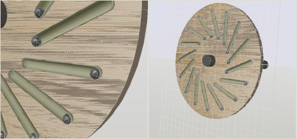
In Fig. 1 is shown yet another kind of "Indian wheel".
Here is shown the disk which is rigidly fixed on the motor shaft. It is assumed that the axis of rotation of the disk is parallel to the earth's surface. On the surface of the disk are attached 16 pipes, closed up at both ends. Inside each tube is placed an iron spherical load. The pipes are placed uniformly over the surface of the disk, symmetrically about the axis of rotation of the disk. The slope of the pipes and the ratio between the internal diameters of the pipes and outer diameters of the spherical loads are such that the loads can move freely within the scope of the pipes under the influence of the gravitational field of the earth.
In the depictions of the disk, as it shown in Fig. 1, the front parts of the pipes were cut away in order to show the places where the loads had been moved under the action of force gravity.
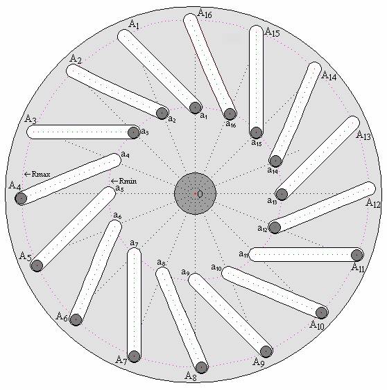
In Figure 2 is shown the section of pipes and loads against the background of the front surface of the disk. Symbols a1 — a16 and A1 — A16 indicate the location of the centres of gravity of loads at their minimum and maximum distances (Rmin and Rmax) from the axis of rotation of the disk (from the point “O”).
Such design in essence of its mechanical properties is fully consistent with the ancient "Indian wheel" and many subsequent attempts to repeat it. However, it is presented in such a way that it is easy to calculate in a general form the resulting torque force (net torque - the sum of the torques produced by all the loads) on the shaft of the presumptive motor.
To facilitate the calculation it is assumed that all of the 16 loads are identical in weight and spherical shape, i.e. the center of gravity of each load coincides with the geometric center of the corresponding ball. At the same time the radii of the circumferences of minimum and maximum removal of the centres of gravity of the loads from the axis of rotation of the disk (of the point “O”) are related by the relation: Rmax = 2Rmin, points a1 — a16 evenly distributed on the circumference of Rmin, i.e. the angular distance between any two adjacent rays emanating from the centre “O” into these points is equal to 360° ÷ 16 = 22.5°, angle between direction of the linear trajectory path of center gravity of each load and direction of the ray, emanating from the point of “O” and passing through the point “a” corresponding to this load, assumed to be 45° (the direction to counter clockwise is accepted as the positive direction of indication of this angle).
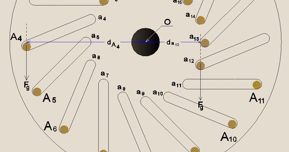
If the force of gravity acting on each load is denoted by Fg, and the shortest distance from the direction of this force to the axis of rotation of the disk (to the point “O”), i.e. lever arm rotation, created by each load is denoted by dn, where n is the digital index corresponding to the number of the selected load (see Fig. 3), then rotary force Mn (torque), produced by each load can be calculated by the formula:
Mn = dn×Fg
Summing torques of all the loads (taking into account the direction of rotation), we obtain the value of the resulting torque (the net torque).
By itself, this calculation, which basically boils down to calculating the values of dn, is simple and quite accessible for achiever schoolboy of a secondary school, who is familiar with the basics of trigonometry. In order to avoid the burdening at the reading this article, I will give here only the findings from the calculation, and the calculation in itself I'll place in the chapter Appendix 1 – Calculation in general form of net torque of the device analogous to "Indian wheel".
Note:
In the process of reading of this section may arise a natural question: “Why had been needed make such a calculation, if long ago have been proved by physicists that, in accordance with Law of Conservation of Energy, the resulting torque of such devices is zero?".
The answer to this question lies in the fact that in the process of finding a way for developing the engine that operates only from environmentally friendly sources of energy it has arisen a desire to find out whether is it possible, in such devices, provide long rotation through the sharing of the kinetic energy of the gravitational field of the Earth with an external force action from another, but also environmentally friendly, energy source. And if it is possible, where and how most appropriate to introduce an external force?
This page was last modified on 17 September 2014